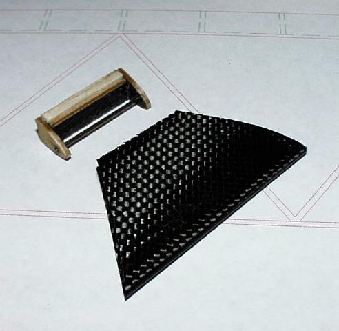
Make the D-box from a single layer of 83gsm carbon. The full-depth spar is a piece of 1.5mm medium balsa or Rohacell 31 with 0.2 mm carbon flanges top and bottom and a single layer of 83 gsm carbon vacuumed onto its rear surface. The stab tends to be somewhat too easy to bend vertically if the flanges are omitted though the torsional stiffness is fine. You also need to install a d/t pivot and probably apply some local reinforcing to the D-box around this area. Here's my solution for an F1J stab:
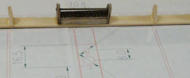
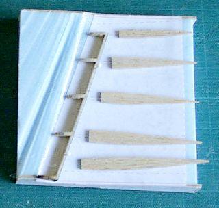
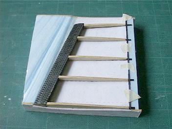
Use medium balsa or Rohacell 31 riblets at about a 25mm spacing inside the D-box. These are important because the stiffness of such a thin shell is critically dependent on the presence of ribs to stop the shell deforming under load. Assemble the spar and ribs to make a fishbone and install it as usual. The next picture shows the fishbone for the F1J stabiliser with the pivot in place ready for insertion in the D-box. This spar has no carbon flanges and the stabiliser feels a bit 'soft' when its bent vertically. At this stage the reinforcement (salvaged from a rejected D-box shell) has been epoxied into the shell.
Russell Peers finds it helpful to add a tiny carbon LE (0.8 x 1 mm) because it holds the riblets in alignment when the fishbone is being installed in the D-box.
See Appendix B for more information about Rohacell.
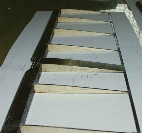
If you are building a VIT or bunt model you may want a much wider centre rib. By making it up to 10mm wide from soft balsa or Rohacell 31, possibly with 0.4mm ply sides and carbon caps top and bottom, you'll find you have an excellent place to install the VIT/bunt lines etc. Its an optimum setup because the forces applied to the tailplane by the d/t band and the various lines are fed straight into a strong member that pivots directly on the stab mount and there is no tendency to twist the rest of the structure. Here is the completed F1J stabiliser, which has straight ribs and is about to have a Lynch bunt system installed in the wide centre rib. This is a Woebbeking section.
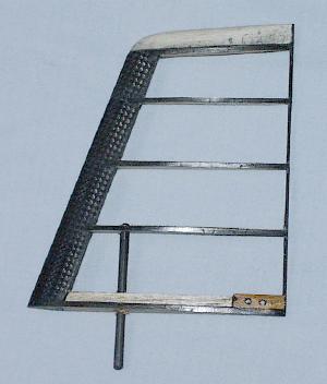
Diagonal ribs are beneficial for a stiff structure. Without them the tailplane may be floppier than the equivalent all balsa structure due to the whippiness of the carbon TE.
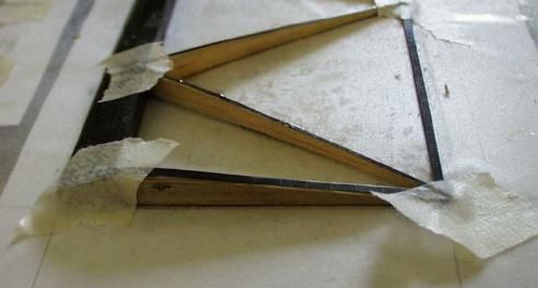
Recent experiments show that straight ribs add little structural integrity in a structure with carbon rib caps. Leave them out and just use diagonal ribs behind the spar. Here's an example, this time for an F1A, and also a Woebbeking section.
Use full chord capstrips on the straight ribs, overlapping the ends onto the LE (or D-box) and TE. Cap the diagonals, overlapping the spar and TE. Cover with mylar or whatever - the structure comes out remarkably stiff thanks to the diagonal carbon and needs no help from the covering in this department.
I made a foam 'half-shell' jig to assemble an F1J fin in. The next picture shows the jig, ribs and fishbone.
This shows the fin after completion of the D-box and addition of the right side capstrips, carbon TE and ribs.
Finally, here's the finished fin.
Remember that all-moving fins tend to have more travel at the TE than a conventional auto-rudder and allow for this when you install the rudder adjusters.
Here's a covering method that works for me. Its not original: I'm fairly certain that M&K thought of it first.
Cut a single piece of mylar that will cover both sides of the stabiliser or fin, allowing extra so the film can be overlapped at tips and under the LE. Mist the structure on both sides with 3M SpraymountTM and allow it to dry.
Lay on the mylar, starting under the LE, wrapping back round the TE and across the top surface. Its quite easy to reposition the mylar to get the wrinkles out. Leave the overlaps at tips and LE sticking out.
Mask off the lower surface with a newspaper, holding it in place with one hand, and mist SpraymountTM on the inside surfaces of the overlap areas. Wait a few minutes for the adhesive to dry and then smooth the overlaps down. Take care not to let them fold over so that two adhesive-covered areas touch because this is very difficult to separate without tearing the film.
Run a finger along the frames to ensure that the mylar is stuck down everywhere it touches the frame and then use a heat gun or covering iron to gently tighten the mylar and remove any remaining wrinkles.