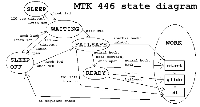
In this diagram the ellipses represent the timer's operating modes. Each arrow represents an event that causes the timer to change from one mode to another. The new mode is pointed to by the arrow. Other events do not cause mode changes and so are not shown in the diagram.
For example, each time the tow hook moves forward or back while the model is being towed is an event (HS opens or closes) that is noticed by the timer but is not shown on the diagram because the timer remains in FAILSAFE mode while circling on the line regardless of how many times you pull the model straight and then let it circle again. There are only three events that can cause the timer to switch out of FAILSAFE mode and these are shown:
The rectangles within the WORK mode ellipse represent the three sections of the FLIGHT program that define timed servo movements. They have been diagrammed separately to show how events that put the timer in WORK mode may cause it to start at different points in the list of servo movements and to emphasise that, when this happens, earlier servo movements are skipped over entirely. Hence you cannot rely on a servo movement in the start and glide sections being carried out on all circumstances. This is not important if the MTK bunt mechanism is being used, but may have implications for other types of mechanism.
There are three events that cause a change from READY to WORK mode and two look more or less identical:
There are no mode changes associated with the OLA system, so OLA does not appear within this diagram.