by Martin Gregorie, © 2002.
An electronic thermal detector is a sensitive and rapidly responding thermometer capable of displaying air temperature variations of 0.2 C to 2 C from the ambient temperature. However, these small differences are mixed with large masking influences, so unless the detection system is designed to eliminate these effects it will give misleading results. This may seem obvious, but if the detector is to reliably show these variations it must be insensitive to changes in solar radiation due to the sun coming and going behind clouds and to wind speed. The traditional 'sweaty armpit' method of thermal hunting is strongly influenced by these effects and so the value, if any, of an electronic thermal detector must be solely that it is unaffected by these factors.
The temperature sensing thermistor must be shielded on both sides and top so that direct radiation can't affect it. An easy solution is to mount it inside a bottomless box made of hard 3 mm balsa which is covered by a 6 mm layer of Styrofoam with an outer reflective layer of aluminium foil. Metal, plastic and fibreglass tubes all transmit radiation. Metal re-radiates received energy on its inside and most plastics are translucent to infrared. If the detector head is being used close to a runway or other bare surface then reflected radiation is also a problem. Mounting a small reflective shield closely below the thermistor so that the bead can't be seen from below will eliminate reflected radiation. I use a 10 mm square of 0.8 mm ply with chrome tape on its underside. It is also important to avoid locating dark pieces of plastic, etc., close below the detector or using them as part of its mounting. I found that a 30 mm diameter black plastic cap, fitted 50 mm below the detector, was re-radiating heat and sending 'mini-thermals' up into the detector. The effect was that about a minute after the sun came out a constant high reading appeared. Removing the cap cured this.
These are all caused by heating due to the current flowing through the thermistor. A 4.7K ohm thermistor connected across a 9v battery, a typical set up, must dissipate 17 mW; a process which warms the thermistor above air temperature. Hence a gust blowing past the device cools it and this shows up as a false temperature drop on the meter. The solution is to use as high a resistance thermistor as possible, but certainly not less than 50K ohm. If a 2M ohm device is used the power to be dissipated drops to 0.04 mW and the wind cooling effect is reduced to 0.25% of that expected for a 4.7K ohm thermistor.
However, there is a downside. The detector shows stability problems as soon as a resistance of 2M ohms is put across the end of 5 to 10 metres of multi-core cable. The instrument becomes skittish as hands are put near the wire. The solution is to use a masthead amplifier so that the wire 'sees' the 100 - 200 ohm output resistance of this instead. Fortunately, integrated circuit operational amplifiers are now easy to obtain as well as being small and cheap.
Some years ago Paul Lagan pointed out that ground effects, especially turbulence and mixing, occur at up to 4 metres above the ground and that for reliable readings the detector should not be less than 5 metres above the surface. I'm not sure how important this is, but I notice that nobody mounts a mylar streamer lower than this.
I like like the thermistor system to compensate automatically for day temperature changes so that I don't have to keep re-zeroing the system all day. Where most circuits compare the thermistor resistance with an ordinary resistor, a device that has been designed to minimise the effect of temperature changes, I use a second thermistor that tracks average ambient temperature. This is achieved by putting the reference thermistor in an air bath within a block of aluminium alloy.
The size and shape of this block is not critical. I've successfully used:
Both thermistors are mounted on either end of a cork plug. This is then fitted into the hole in the alloy block so that the reference thermistor is sealed inside the air bath without touching the block and the sensor thermistor is in free air.
The final point concerns response speed. The smaller the thermistor, the faster it responds. 1 mm glass surfaced bead thermistors work well. I use them as received though some other flyers have been known to file the glass skin off. Some thermistors come mounted in a hollow glass sphere, which is sometimes evacuated. This must be removed because these devices are designed to measure thermal radiation and are rather well insulated against changes in air temperature.
Thermistors that are much bigger than a 1mm bead are useless for thermal detection. The commonly available bead thermistors with heads of 3mm to 4.5mm diameter are probably too big for a good response rate despite being designed for precision temperature measurement; their thermal constants are of the order of 10 to 12 seconds. Still bigger thermistors are available, but they possess far too great a thermal inertia and too low a resistance to be useful for our purposes.
I've been using a device designed with these principles since the start of the 1980 flying season. Its features are:
My system is designed to be used with the control unit placed on the ground at the flight line. The masthead unit clips onto a DIN plug that is permanently attached to the top section of the roach pole. An internal cable connects it to a 3-pin DIN socket let into the base section of the roach pole. Ten metres of three wire cable, fitted with the 3-pin DIN plug at each end, is used to connect the pole to the control unit.
Other arrangements are possible; the physical arrangement will depend on where you mount the control unit. Many flyers attach it to the roach pole with a Terry clip. This type of arrangement would need a much shorter cable with at most one plug in the cable. I've also built a portable version with a carbon F1A tail boom extending from the hand-held control box and a DIN socket on its end to connect the masthead unit.
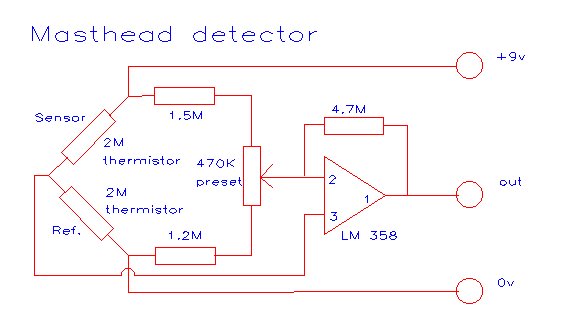
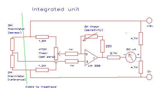
The two thermistors form one arm of a Wheatstone's Bridge circuit. The other arm consists of the two high value resistors and the preset, which is used to set operating conditions so that when the detector is stabilised at a constant ambient temperature the masthead amplifier's output voltage will be half the supply voltage. The masthead amplifier provides some gain to counteract the losses in a long cable, but is primarily to act as a low impedance voltage source in place of the high impedance Bridge circuit.
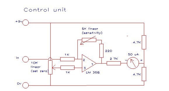
The control unit drives the display, a moving coil microammeter, contains the battery needed to operate both parts of the detector, and has the controls needed to set the zero reading and sensitivity of the thermal detector to suit the conditions of the day. It contains another amplifier, this time with variable gain and offset controls, to drive the meter.
Both circuits are easily laid out on copper striped Veroboard.
All components except the thermistors are soldered into the masthead board. Use a flat-mount 470K preset because you'll need to get access to it when the masthead circuit is installed in its solar shield. If your thermistors are not 2M ohm types you should scale the other resistors in the bridge circuit (shown as 1.5M, 1.2M and the 470K preset) to match. For instance, if 100K thermistors are used these resistors would become 75K, 62K and 24K preset.
Use the biggest and most readable microammeter you can find for the control circuit display. Edge-display meters are the best if you can find them. The scale of the meter is not critical. I've always used a standard 0-50 or 0-500 uA microammeter, but interactions between the Set Zero and Sensitivity controls would be minimised if a center zero meter was used and the 'cold point' was set to the meter's zero point.
The pins used in this application (pins 1-3) are shown on the diagrams. Power connections to the LM358 operational amplifiers have been omitted for clarity. They are:
| pin 8 - +ve power supply |
| pin 4 - 0v (ground) |
Other pins may be left unconnected.
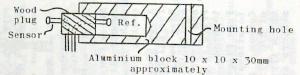
Thermistor mounting detail 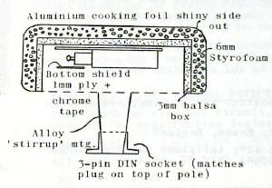
Cross section of the masthead assembly |
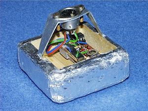
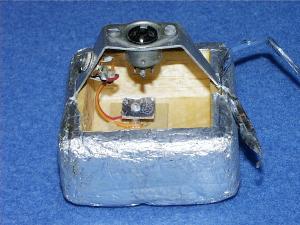
The 3-pin DIN socket on the alloy sheet support attaches the masthead unit to the top of its 5 metre roach pole as well as providing electrical connections. The reference thermistor is inside the small alloy block on the left side of the circuit board. The sensor thermistor is underneath the chrome tape covered piece of hard balsa projecting from the top of the alloy block. |
 |
 |
|
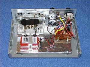
Control unit interior. Plenty of space and everything is well tied down to prevent damage during normal use. |
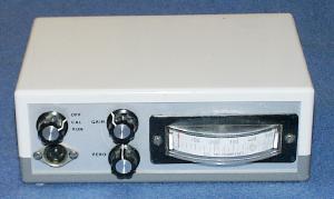
Control unit exterior. The edge display microammeter is easy to read while preparing to start and launch a model. |
The initial step is to install a fresh 9v battery. Set the system up indoors and leave it for 15 or 20 minutes while the thermistors warm up and the alloy block stabilises at the ambient temperature. Make sure that direct solar radiation can't shine into the interior of the masthead unit during this procedure. Now adjust the masthead preset so that the amplifier output voltage is 4.5v.
In normal use assemble the system, turn it on and allow it to stabilise for 15 minutes or so before you need to use it. The Set Zero control is used to set the 'coldest' reading on the meter. A good point is 10% to 20% of the full scale reading. The Sensitivity control should be adjusted so the strongest thermals show about 80% of full scale. Take note that these two controls will interact unless Set Zero is set to zero on the meter.
Once the meter has been set up for the day the only control that should need adjusting is Sensitivity. As the day wears on the temperature swing in thermals will steadily increase until late afternoon and then start to decrease. Adjust Sensitivity to keep the highest thermal temperature around 80% of full scale.
If the chosen physical arrangement is a portable unit or has the control unit mounted on the detector pole so that the cable to the masthead will not exceed three meters in length then the following circuit can be used:
This is an easier circuit to set up because there is no mast-head amplifier to adjust. Normal operation is identical to the previous design. The same remarks apply to adjusting the Wheatstone's Bridge resistor values to match the thermistors.
Digital temperature modules, such as those sold by Maplins in the UK, can be used for thermal detectors, provided their sampling rate is fast enough. There are a few problems which will prevent these devices being useful:
The Maplins temperature module is perfect for this application. It runs for several years off a single AA sized battery, can be set to a 1 second refresh rate and can display temperatures in Fahrenheit or Centigrade. It will require mounting in some sort of enclosure and switches to be added to select the display mode and temperature scale and set its internal clock. It has an optional external probe with a very bulky probe, but the internal thermistor, which must be unsoldered to fit the external probe, is a very small bead thermistor and perfect for thermal detection.
Before fitting an external probe other than the manufacturer's accessory it is necessary to understand how these units work. Unlike the analogue circuits described above, digital modules don't measure thermistor resistance directly. Instead, each time they refresh the display they cause the thermistor and its cabling to resonate for three or five sine wave cycles and measure the time this takes to complete. By treating the cable and thermistor as an RC tuned circuit and assuming that the capacitance of the cable is known, its possible to calculate the resistance of the thermistor, and hence its temperature, from the resonant frequency. The effect of this is that the displayed temperature is affected by any changes in the length or type of cable used to connect the thermistor to the module. As the cable gets longer or its capacitance per unit length is increased the displayed temperature rises until the limiting case, when the module will go off scale. The workarounds are:
Once a suitable cable and pole arrangement has been found all the remarks about shielding the thermistor from solar radiation in the introduction apply to digital as well as analogue systems. The shielding techniques work equally well for both types of thermal detector.
A digital masthead is shown in this picture. It is designed to fit on a thermal pole that was built for use with the analogue thermal detectors described above. In consequence it is mounted via its 3-pin DIN socket, but this is not used for the electrical connections due to the high capacitance of the pole's internal wiring. Instead, the 80 ohm ribbon connects to the thermistor via the 3.5mm jack plug mounted in the alloy support. The mylar ribbon tied to the unit is a wind direction indicator, fitted in an attempt to improve my power model launches.