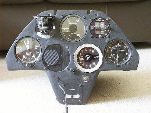
My Libelle came with a reasonably well-equipped panel. Apart from the usual ASI, altimeter, compass and slip ball, it was fitted with a Cambridge Mark 4 vario and speed director (top centre and right) and a PZL mechanical vario. The blank position next to the altimeter and the wire beneath it were used for an ICOM hand-held radio, which was powered from the glider battery and mounted on the Velcro pad. It was fitted with a remote speaker/mic unit and connected to the Libelle's built-in antenna.
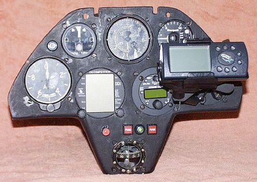
I rebuilt the panel before I flew the Libelle for the first time because I wanted to replace the Cambridge instruments vario with my SDI C4, which had been retrieved from the ASW-20 and fully overhauled in Germany. I also wanted to move the ASI to the top centre of the panel.
I rapidly found that I'd need to change the mounting points to accomodate the C4, so I took the opportunity to completely strip the panel, fill unwanted holes with balsa and fibreglass and to repaint the front and underside of the structure. I made up a data interconnect box that links the Garmin GPS II+ and the C4 with provision to feed GPS data to an EW model D logger and an iPAQ PDA. It contains a 5v switch mode power supply for an iPAQ and distributes power to the C4, GPS and logger. One thing leads to another, so the PZL vario was replaced with a Borgelt B.40, which makes a good backup thanks to its internal battery. It is fully compatible with the C4 because both varios use solid state pressure sensors rather than capacity bottles. I installed a Filser ATR 500 radio alongside the C4, where its partly obscured behind the GPS. I also decided that I needed a Turn & Slip as a safety measure for wave flying and, after consultation, decided to install it to the left of the ASI. This, in turn, required the Winter slip ball to be removed to make way for a Ludolph compass. I fitted a strong blanking plate to the right lower position and use it as an attachment point for the GPS II+ mount. The GPS II+ is connected to an active antenna which is mounted on an alloy support behind the panel. The four knobs in the centre are the C4 audio volume, radio and T&S fuse, the master switch and fuse for the varios and GPS. The T&S is controlled by the push switch to its lower left.
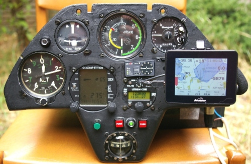
I'm very pleased with the result. The panel is easy to scan, especially on finals in turbulent conditions. During normal flying the C4 and B.40 varios complement each other very nicely. The C4 provides the musical accompaniment and a vast array of information about average climb rate and trends, wind, L/D and final glide while the B.40 gives a very rapid response that's helpful for rapidly centring up small thermals.
This rearrangement was carried out in order to fit an LX Red Box FLARM unit. I wanted to fit the FLARM display as high as possible, which meant under the ASI. To accommodate it the radio needed to be dropped so its lower edge was level with the bottom of the C4, which required filling the 80mm mounting hole it occupied and cutting it a new 57mm hole. Everything else could have been left alone as little else had changed since my initial rebuild except that the GPS II+ had been replaced by a Binatone B.350 PNA running LK8000. However, I took this opportunity to block off the right-hand 80mm mounting hole as well and to move the Binatone flexi-support's attachment point to the edge of the panel because this freed up enough space between the radio and the Binatone to fit a 57mm transponder, should this ever be forced upon us. Both holes were closed with a ply/balsa sandwich, epoxied in place and finished with 100 gsm glass cloth that extended onto the original structure on both front and back surfaces. The cut-outs and mounting holes for the FLARM display, the FLARM's SD card reader, which is fitted just to the right of its display, and the radio were cut before the panel was refinished in matt black enamel.
The Red Box electronics is attached to the same alloy support as its GPS antenna behind the panel.
This only left the problem of what to do about the FLARM transceiver antenna: it can't simply be mounted on or near the FLARM itself because the top row of instruments would prevent it 'seeing' FLARM-equipped gliders lurking behind me. After a discussion with Thorsten Mauritsen, a Danish Libelle pilot, I decided to try his solution and built a FLARM dipole mount similar to his. At the time of writing I'm still collecting and processing FLARM reception data to fine tune the dipole position, but the system is generally working well and I'm very pleased with the panel layout.
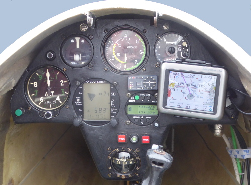
The ATR-500 radio was replaced by a Dittel KRT2 in 2013. This was a pre-emptive strike caused by the mandatory change from 25 kHz channel spacing to 8.33 kHz spacing.
The wiring was modified while the radio was being changed so that all instruments and wiring can be removed from the panel without any soldering or wire cutting. This makes trouble shooting and equipment swapping a lot easier. For this to work, all instruments that require power or data connections must be connected to a single distribution box and never to each other. Each instrument's cable(s) is terminated with a single multi-way Maplins plug that mates with a chassis socket on a distribution box and is locked into its socket by a screw-down ring. All data interconnections are within a single box, though it proved more convenient to add two more small distribution boxes that are only used for 12v power. The instruments they supply do not provide or or consume data.
The Binatone B.350 PNA was replaced by a Medion S.3747 PNA in 2014. The Medion has a transreflective display and is much easier to read with direct sunlight on its face than the Binatone ever was. As a bonus it also has a larger capacity, easily replaceable battery and the micro-SD card containing LK8000 is installed behind the battery so, unlike the Binatone's SD card, it can't be accidentally ejected.