This section describes how to make a spar. It assumes that you have already designed the spar and so you know what materials you are intending to use and that the dimensions of the spar are already determined. Appendix A gives some rough guidance in spar sizes.
A glider spar is designed to handle extreme bending loads. It has several parts:
The joiner block fits between the spar flanges and is drilled for the joiner rod. If I'm building an F1A glider, I buy the M&K joiner assembly, which consists of the pair of carbon blocks and a 5.8 mm joiner rod. The blocks are preformed to fit the rod. For F1J you could fit an aluminium tube into a hard balsa section in the web. A 3 mm carbon rod makes a good joiner for a small to medium sized F1J.
The spar is either whipped with Kevlar thread (new material and technique, no new tools) or put inside a woven carbon tube which is then wetted out with epoxy and clamped to compact it while it cures.
For spar assembly you will need:
Everybody needs a Dremel. Its one of those tools that, once bought, you wonder how you managed without it all those years.
The important thing in spar assembly is to keep the spar straight and square and to have nice flat surfaces. The top and bottom flatness is vital as the most important joints in the wing are the spar to D-box ones. These take all the bending and torsion loads. The rear surface, too, should be flat to make it easier to attach the ribs.
I start by lightly sanding both surfaces of all carbon sheet components to remove traces of release agent followed by careful dust removal. Scrub the carbon in water with a nail brush (the bath is a good place to do this) and de-grease it with an acetone wipe immediately before gluing it.
Glue the joiner blocks onto the bottom spars with 24 hour epoxy. Use Araldite or DP460. As in all spar assembly, use just enough epoxy to make a good joint; too little gives a dry joint and too much is both weaker and heavier than necessary. Do this assembly on the L jig with the joiner slid into the blocks to ensure that both spars and joiner blocks are correctly aligned.
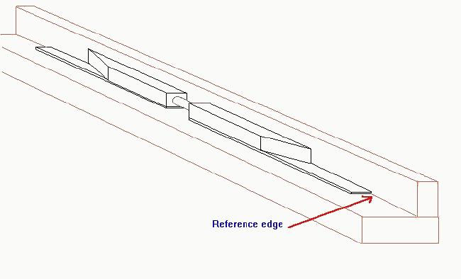
Accurate alignment of joiner/blocks and one edge (the reference edge which is accurately at right angles to fuselage datum) of the flanges is vital if your wings are to fit correctly. Once the joiner blocks have been glued to the lower spar there is no going back. Choose this edge so it runs accurately spanwise in the wing; I use the rear of the spar as the reference edge. Mating surfaces of joiner block and spar should be lightly sanded to remove release agent, but be careful sanding the joiner blocks or you can destroy their mutual alignment. Put release film between the L-jig and the area being glued. After applying the epoxy and making sure that everything is lined up I tape the spars and joiner blocks in place with masking tape. This drawing shows the general setup.
I assemble the web from slices cut across medium to light 100 mm balsa sheet. The slices should be a bit over twice the final web depth for each spar. You will be cutting the completed assembly lengthways to give two partially completed spars, so allow enough excess width in the slices for sanding to true up the edges and to give yourself enough slack to separate the spars, but not so much its a pain to sand them down later. After sanding the edges true and parallel I trim one end to match up with the joiner blocks and epoxy both bottom flanges to this block, using the jig and clamp strip. I align one of the balsa block surfaces with the reference edge of the spars and let the block overhang the other edge. Use 24 hour epoxy for the assembly and don't forget the release film. Tip spars are treated exactly the same apart from the absence of joiner blocks. The following drawing should clarify the way the spar assembly is set up:
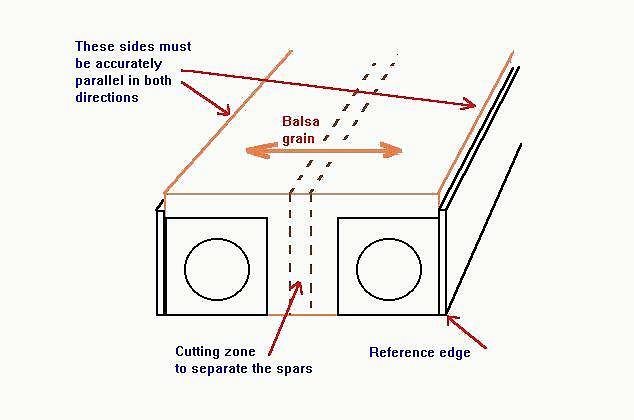
When the assembly is cured it is carved and sanded so that both sides are flush with the edges of the spars, giving a tapered block of balsa with carbon on each edge. This is then separated lengthways down the middle of the balsa web to reveal the top edge of each spar's web. Use a sharp knife and cut accurately. If you crush or cut into the part of the block that will form the web you've ruined the spar.
The top edge of each web is now sanded to the exact depth and angle required for the completed spar to fit precisely between the D-box surfaces. The top of the joiner block is sanded at the same time so that it is an accurate continuation of the web. Take care with this; the integrity of your wing depends on the fit and adhesion between the spars and the joiner block. Remember to allow for the thickness of Kevlar wrapping or carbon sock when you are calculating this. The depth you require is:
     sanding depth = section thickness
                     - 2 * D-box thickness
                     - 2 * sock thickness
                     - upper spar thickness
The angle between the flanges depends on the section and spar position. In my current design the spar is placed where the upper and lower surfaces are parallel. Whether this will suit you depends on the section and how wide a D-box you want to use. In any case the spar web's upper surface must be sanded to an angle and thickness that place puts the outside surfaces of the completed spar precisely parallel to the inside surface of the D-box without requiring the latter to be forced into contact with the spar. My sanding rig is something like this:
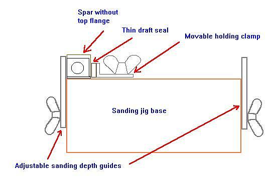
I use a slider to support Permagrit sanding material so that the Permagrit doesn't cut into the sanding guides and ruin the jig.
After sanding the web the top spar flange is glued on using 24 hour epoxy. Place the assembly reference side down on the L-jig so that the two spar flanges are accurately aligned by their reference edges. Use release film.
The web should be pretty much flush with the spar flanges on each side. Sand off any excess epoxy on the surface of the web.
Now its time to fit the 'sock'. This is carefully slid onto the spar and pulled tight. I temporarily attach tapered balsa blocks to each end of the spar, dope them and sand them smooth to stop the sock from snagging. The sock is wetted out with laminating epoxy. This is blotted out as much as possible with kitchen towel and a rolling pin, the spar is wrapped in release film, put on the jig, and the weights hung on the free ends of the sock. I compact the spar on its side using an alloy U extrusion to clamp the flanges (side to side on the jig) and a balsa strip to clamp the sides (top to bottom on the jig). This arrangement works just fine with parallel flanges and a spar that tapers in depth, like a tip spar. I'd use a dense sponge rubber, such as draft excluder strip, to apply pressure to the top of the spar if the flanges were not parallel.
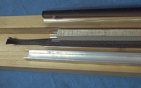
When the epoxy has set the spar is trimmed to length and lightly sanded to let the glue key really well. The following picture shows the parts I use to clamp up the sock.
The next picture shows (from the top) a finished test sample, two tip spar cores with the sock guides fitted and a sample of 10 mm diameter sock. The cores look dark because finish sanding them generates carbon dust that gets embedded in the balsa web and sock guides.
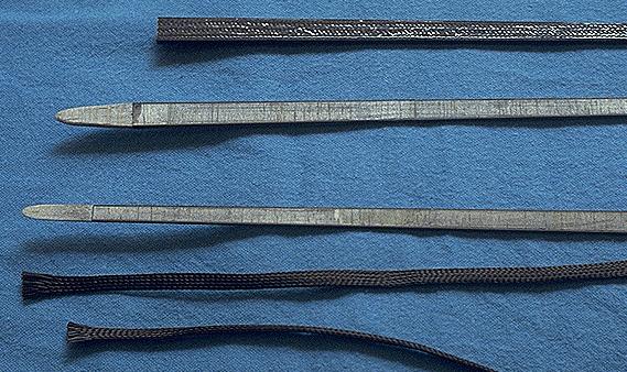
I use 10.0 mm diameter sock on tip spars and 15 mm diameter on inner spars. The diameters are quoted with the threads at 45 degrees; the 10 mm sock can vary from 3 to 13 mm diameter depending on how its pulled or shortened.
NOTE: the sock sold by Aerospace Composite Products is much larger than this and is unsuitable for our spars. My sources are Mike Woodhouse and Gerhard Aringer (on the flying field), though Matt Gewain of Composite Structures Technology may also stock suitable material.
You should make up a test piece before attempting a 'real' spar so you have some idea what you're getting into. Measure its depth accurately before applying Kevlar wrap or carbon sock. Do a full dress rehearsal using the jigs, clamps, and release film. Measure the overall spar depth again and you'll know the 'sock thickness' needed to calculate the sanding depth.
An F1J spar can be considerably simpler than a glider spar because it carries much lower loads unless you make a habit of d/ting off the top with no delay between the engine stopping and the d/t. Under normal use the largest loads will be d/t landings and getting blown over on the ground.
The most thats needed is:
The flanges are cut a little oversized and glued to the top and bottom edges of the web with epoxy or cyano. Once the glue is set they are sanded to the same width as the web. Install the joiner tubes by slotting them into the web once the spar flanges have been glued on. I would use harder balsa for the root section of the web so that I can remove a section and epoxy the tubes into the web, taking account of inner panel dihedral and jigging the spars while the epoxy cures.
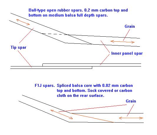
Phil and Anthony Ball build open rubber wings using medium balsa full depth spars. The grain runs spanwise with 0.2 mm (.007") carbon sheet stuck to the top and bottom edges. Dihedral joints are made by overlapping the spars enough that the tip spar top surface ends where it meets the inner spar lower surface and vice versa. This is very strong. An interesting experiment for F1J could be to splice the inner and outer spars together to form a single 3 mm balsa item, add 0.2 mm carbon top and bottom and then slip sock over the lot. Might need care to get it round the dihedral break without snagging but the result should be very strong.